Presentation of a Network Diagram designed based on the OSI model
Honghong Liu, MSc, CSCMP, PMP
Sr. Sourcing Specialist (IT) at Ontario Health
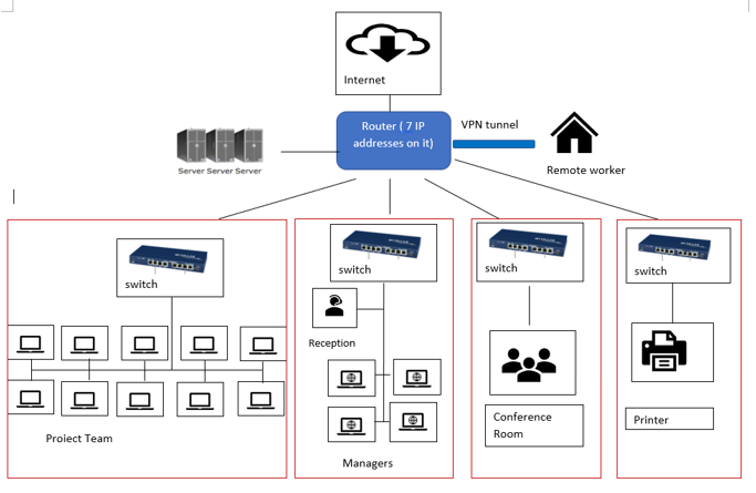
I am presenting a simple network diagram I designed. We require a network for the following working areas: A reception area, 4 offices for management, 1 conference room, 10 work stations for the project team, 1 printer and a computer room which hosts several servers. My design was based on the OSI (Open System Interconnection) model. In the following sections, I will elaborate how each layer of OSI is represented in the network diagram.
Network Diagram
The network diagram is depicted below.

Layer 1 – Physical Layer
The physical layer of a network contains all the hardware used in a network, such as cabling and patching. In the design, patch cables are used to connect work stations with the switch within each subnet, and which is represented in each red box in the above diagram. The connection between the router and the four (4) switches and between the router and servers are through Ethernet crossover cables.
Layer 2 – Data Link Layer
In the data link layer, the data move into and out of a physical link in a network. The data link layer provides the functional and procedural means to transfer data between network entities and might provide the means to detect and possibly correct errors that may occur in the physical layer.
In my design, communication between work stations within a subnet and communication between subnets are on the same local area network (LAN) segment.
Layer 3 – Network Layer
“The network layer provides a logical network on top of the physical network. It defines the route via which the data is sent to the recipient device” (Laan, 2013). This is the layer in which IP protocols, such as routing, switching and addressing are implemented.
In a network, each device connected to this network is assigned an IP address. An IP address services two principal functions: host (hardware in a network) identification and location address.
Very often a network gets too big, with devices constantly added to the network. That is when subnetting is used to split up an IP network into two or more smaller subnets, each forming a new IP network, and each identified by a subnet mask. A Subnet mask is a 32-bit number that masks an IP address, and divides the IP address into a network address and a host address. Devices with the same network address can connect to each other directly. Devices with different network addresses need a router to connect. Using the subnet’s mask, IP address spaces can be used more efficiently.
In this design, subnetting was used to divide my client’s network into four (4) subnets, each with its own IP address and subnet mask. I used a router to connect all four networks, so that packets can be forwarded to the network where they are destined for, based on the address information in the packets, specially the destination IP address.
Layer 4 – Transport Layer
“The transport layer maintains flow control and provides error checking and recovery of data between network devices.” (Laan,2013) “The transport layer is also responsible for the management of error correction. This layer enables the host to send and receive error corrected data, packets or messages over a network.” (Techopedia)
In the layer above – the Network Layer - due to network disruptions, IP packets can get lost or corrupted. The effects of lost and corrupted IP packets are handled by protocols like TCP (Transport Control Protocol) in this Layer 4.
Layer 5 – Session Layer
“The session layer provides the mechanism for opening, closing and managing a session between end-user application process.” (Laan, 2013)
Since employees may work remotely from time to time, I also added a VPN (Virtual Private Network) tunnel to the network. I used the virtual connection based on IPsec/SSL (Secure Sockets Layer). Wherever the internet is available, remote work stations can create a VPN tunnel to my client’s headquarter.
Layer 6 - Presentation Layer
The presentation layer is responsible for the delivery and formatting of information to the application layer for further processing or display. This layer takes data from other layers and converts it into a standard format that other layers can understand.
The company's correspondence with clients can be highly confidential, so messages require encryption prior to sending and decryption upon receiving. I have designed to use SSL (Secured Socket Layer) to implement encryption and decryption.
Layer 7 - Application Layer
“The application layer interacts with the operating system or application whenever the user choses to transfer files, read messages, or perform other network related activities.” (Laan, 2013).
In the case of the company I designed for, the following activities take place in Layer 7:
- we exchange messages within the company using LAN and outside the company using WAN and Internet;
- we manage our online presence throughout the website, using Internet;
- we access shared files and manage them.
Conclusion
This article has briefly explained the function of each layer of the OSI model, and the representation of each layer in the network diagram. I think that utilization of the OSI model in designing the network can provide a common language across departments, i.e. IT, Project Management, Sales and Marketing, etc. within a company.
References:
Techopedia. Transport Layer. Retrieved from https://www.techopedia.com/definition/9760/transport-layer
Laan. S. (2013), IT Infrastructure Architecture –Infrastructure Building Blocks and Concepts. 2nd edition. Retrieved from https://read.amazon.ca