

Research on Optimal Arch Rib Inclination of Large Span Highway CFST through Arch Bridge

1
School of Transportation and Civil Engineering, Shandong Jiao Tong University, Changqing District, Jinan 250357, China
2
State Key Laboratory of Mountain Bridge and Tunnel Engineering, Chongqing Jiaotong University, Chongqing 400074, China
3
School of Civil Engineering, Hunan City University, Yiyang 413000, China
4
Smart Sensors and NDT Laboratory, Department of Civil, Materials, and Environmental Engineering, University of Illinois at Chicago, W. Taylor Street, Chicago, IL 60607, USA
*
Author to whom correspondence should be addressed.
Buildings 2023, 13(6), 1415; https://doi.org/10.3390/buildings13061415
Submission received: 25 April 2023
/
Revised: 23 May 2023
/
Accepted: 29 May 2023
/
Published: 30 May 2023
(This article belongs to the Special Issue Intelligent Building Health Monitoring and Assessment)
Abstract
:To investigate the reasonable range of the inclination angle of arch ribs, a spatial finite element method was employed based on a concrete-filled steel tube (CFST) basket-handle through an arch bridge with a span of 360 m. A spatial finite element model was established using Midas/Civil software, which was verified with actual bridge data. The effects of different arch rib inclination angles were investigated under static loads. The structural natural frequencies, linear elastic stability coefficients, internal forces, and displacements were comprehensively considered to determine the reasonable range of the inclination angle. The results show that when the inclination angle ranges between 8° and 10°, the first, third, and sixth natural frequencies of the structure are increased. It effectively improves the lateral and torsional stiffness of the arch ribs while ensuring optimal out-of-plane stability of the arch ribs. Compared with the parallel arch, the stability is improved by 20.2%. The effects of angle variation on displacement and internal force of the arch ribs were not significant. Considering all indicators, the optimal range of the inclination angle for the arch ribs of 300-m-level highway CFST arch bridges is suggested to be 8~10°.
1. Introduction
In mountainous regions of China, arch bridges are widely used due to their advantages of high stiffness, high bearing capacity, good seismic performance, and low cost [1,2]. The number of existing concrete-filled steel tube (CFST) arch bridges in China has exceeded 400, and their spans continue to break records. However, there are few CFST basket-handle arch bridges with spans above 300 m [3,4,5]. Therefore, the research on the large-span basket-handle arch bridge is relatively limited, especially on the mechanical performance affected by inclination angle [1,6].
As the span of steel-concrete composite arch bridges increases, the problem of lateral stability becomes more prominent. The basket-handle arch not only has an elegant appearance but also has good lateral stability. Table 1 shows the statistics of some highway CFST basket-handle arch bridges. The inclination angle of the arch ribs is between 4.6° and 13°. Existing literature [7,8,9] has shown that if an improper inclination angle of the basket-handle arch ribs is used, the lateral stiffness decreases. In addition, for truss structures, changes in structural form may lead to a redistribution of member axial forces, thereby affecting the safety of the structure. Scholars have proposed methods to estimate the axial forces on the members of the structure. Therefore, when determining the optimal inclination angle of the arch ribs, the effects on the mechanical performance, such as axial forces and bending moments of the structure, need to be considered [10,11]. Many scholars have studied the effects of inclination angle on the structural mechanical performance of CFST arch bridges. Yang et al. [12] studied a 220-m railway CFST arch bridge with varying inclination angles. It was found that when the inclination angle ranges from 0° to 10°, the modal frequencies of lateral and torsional vibrations of the arch ribs increase with inclination. However, the vertical and longitudinal vibration frequencies remain almost constant. Yun et al. [13] used the finite element analysis method to study the influence of the arch ribs rise-to-span ratio and inclination angle on the structural vibration mode and stability. A mid-supporting steel-concrete composite arch bridge was employed in this study. It was found that the inclination angle of the arch ribs should not exceed 10°. Wang et al. [14] conducted a self-vibration characteristic analysis of a 240-m railway CFST arch bridge. In this study, the lateral vibration frequency was found to be more sensitive than the other two directions when the inclination angle varied from 7.5° to 9.5°. Wei et al. [15] conducted a parameter analysis of several existing CFST arch bridges and built a CFST arch bridge with a span of 105 m. The study showed that the linear elastic stability safety factor gradually increased as the inclination angle of the arch ribs increased within 0–15° and reached an optimal state at 9°. Zeng et al. [16] studied the structural stability of a steel box arch rib bridge with varying arch rib inclination angles from 0° to 12° using the finite element analysis method. The results showed that the out-of-plane stability safety factor increased first and then decreased with the increase in inclination angle. The out-of-plane stability safety factor reached its peak at 10°. However, the in-plane stability safety factor decreased with the increase in the inclination angle. Therefore, it is necessary to comprehensively analyze and determine the optimal inclination angle. Zhao et al. [17] studied the variation of internal forces at key positions of the arch ribs when the inclination angles were 0°, 7°, and 15°. A flying-swallow-shaped CFST cable-stayed arch bridge with a main span of 360 m was employed in this study. The results showed that the internal forces of the arch ribs increased with the increase in the inclination angle, especially the bending moment at the crown. Huang et al. [18] examined the variation of internal forces and vertical displacement of a 260-m CFST arch bridge when the inclination angle of the arch rib ranged from 0° to 12°. The results showed that with an increase in the inclination angle of the arch rib, the bending moment and horizontal thrust force at the abutments decreased significantly, reaching a minimum of 8°. The increase in inclination angle beyond 8° did not result in a significant change in the internal forces or vertical displacement. Xu et al. [19] used a railway CFST arch bridge as an example to investigate the influence of the arch rib inclination angle on the seismic performance of the structure. The study found that an inclination angle of 3.5~4° not only reduced the displacement and axial force of the arch rib but also avoided the problem of excessive growth of tensile stress in the concrete of the arch rib, which could result in inadequate strength. Wang et al. [20] determined the optimal inclination angle of the arch rib by considering the effects of the rise-to-span ratio, width-to-span ratio, and number of transverse braces. A centrally supported dumbbell-shaped steel-concrete composite basket-handle arch bridge was employed in this study. The study found that the optimal inclination angle of the arch rib was negatively correlated with the rise-to-span ratio and not significantly correlated with the number of transverse braces. Ji et al. [21] investigated the variation patterns of the linear elastic and ultimate bearing capacities of a large-span railway steel-concrete composite lever arch bridge with a tube-shaped structure. The study found that the structural stability of the arch bridge would increase first and then decrease as the arch rib inclination angle increased. The optimal value of the inclination angle was determined in this paper as well. Pan et al. [22] conducted a study on the influence of the inclination angle on the lateral stability of a tied arch bridge using the finite element method. Through parameter analysis, the study obtained an approximate expression for the reasonable inclination angle of the double-rib arch. The studies of the aforementioned scholars have achieved rich results. However, the majority of studies were focused on railway bridges. Related studies on highway bridges are relatively few, especially for bridges with spans larger than 300 m. Furthermore, the evaluation is not comprehensive enough. The relationship between multiple factors of the structure and the arch rib inclination angle needs to be systematically studied. Further research is required to comprehensively determine the reasonable range of inclination angles for the arch rib.
The objective of this paper is to study the influence of the arch rib inclination angle on the large span highway CFST basket-handle arch bridge (i.e., 300 m level). The mechanical performance of the structure under different rib inclination angles was investigated. A reasonable range of arch rib inclination angles for large-span CFST arch bridges was proposed to enhance their safety and provide a reference for the design of similar bridges in the future. Based on the world’s largest CFST basket-handle arch bridge with a span of 360 m—the Shaowei Zuojiang Extra-large Bridge—this paper employs Midas Civil to establish a full-bridge finite element model. Firstly, the accuracy of the finite element was verified by using the measured vertical displacement values of the main arch during the installation of the main beam and bridge pavement. Then, different arch rib inclination angles were simulated in the FE model. The structural vibration characteristics, linear elastic stability, internal forces, and displacement under static loads with different inclination angles were analyzed. The relationship between the arch rib inclination angles and the structural mechanical performance was systematically studied.
2. Bridge Background and Finite Element Model
The Shawei Zuojiang Bridge is a through-arch bridge with varying cross-section CFST truss ribs. It is designed as a basket-handle arch bridge. It has a main span of 360 m (an effective span of 340 m) and a rise-to-span ratio of 1/4.533. The arch axis follows a catenary curve, and the arch axis coefficient is m = 1.55. The two arch ribs are inclined 10 degrees towards the centerline of the bridge, as shown in Figure 1a. The transverse spacing between the arch feet is 38 m. Each arch rib is constructed from a four-tube truss with a varying cross-section. The cross section has a height of 7 m at the arch crown section and 12 m at the arch foot section, and a rib width of 3.2 m. Both upper and lower chord members of the arch rib are made of steel pipes with a diameter of 1200 mm and a wall thickness of 24–32 mm, filled with C60 self-compacting concrete to compensate for shrinkage. The rectangular cross-section is formed by connecting the chord members of the main arch rib with 720 mm-diameter connecting pipes and two vertical web members with a diameter of 610 mm. The chord members of the main arch rib are all made of Q345 steel.
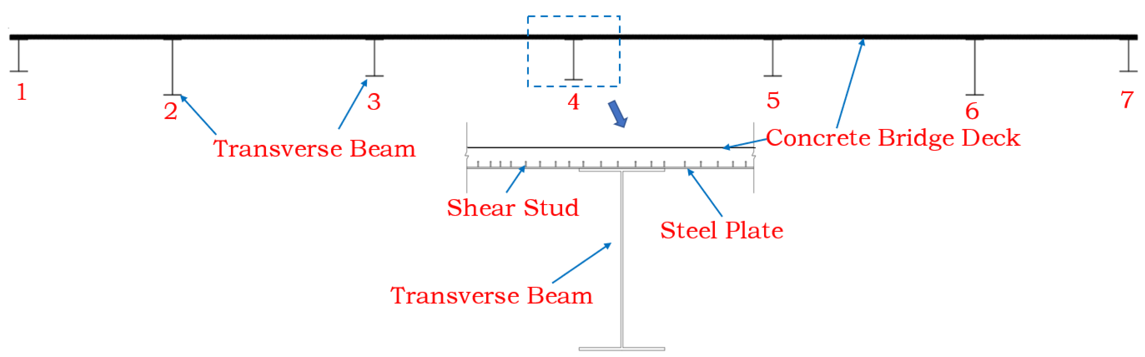
The two arch ribs are connected by “X”-braces. There are 12 “X”-braces arranged along the upper chord and 10 along the lower chord, with the steel pipes of the “X”-braces measuring Φ900 × 18 mm. The cross-sectional diagrams of the main arch rib at the crown and foot are shown in Figure 1b and Figure 1c, respectively, and the overall layout is shown in Figure 2. The cross-section of the bridge deck is shown in Figure 3. The bridge deck has a concrete slab and steel grid beams supporting it. The steel grid beam consists of 7 longitudinal beams and 24 transverse beams. The transverse beam is made of 20-mm-thick steel plates and is located under each suspender. The longitudinal beams are I-beams made of Q345 steel. The thickness and the width of the top and bottom flanges of the longitudinal beams are 20 mm and 600 mm, respectively. The thickness of the web plate is 16 mm. The No. 2 and No. 6 beams in Figure 3 have a height of 1924 mm. The No. 1 and No. 7 beams have a height of 1113 mm. The No. 3 and No. 5 beams have a height of 1274 mm. The No. 4 beam has a height of 1400 mm. A C40 concrete slab with a thickness of 140 mm is located at the top of the grid beams. The steel grid beams and concrete slab are connected by a steel plate with a thickness of 100 mm and shear nails. The entire bridge has 24 pairs of suspenders, which are composed of steel strands with a tensile strength of 1860 MPa. This type of through-arch bridge has a clear load path. The dead load and live load are transmitted to the arch ribs through the suspenders and then to the abutment at the arch foot.
MIDAS/CIVIL is software for structural and spatial finite element model building. It was wildly used in bridge construction, temperature, dynamics, and mechanical performance analysis [23,24].
In this study, the finite element software MIDAS/CIVIL was used to implement the spatial finite element modeling of the bridge. The appropriate spatial elements were selected based on the actual stress conditions of each component. The corresponding constraints were applied according to the boundary conditions. The following assumptions were made in the modeling process: (1) all section deformations comply with the cross-sectional assumption; (2) no slippage occurs between steel tubes and concrete; and (3) linear elastic theory is adopted and nonlinear effects are not considered.
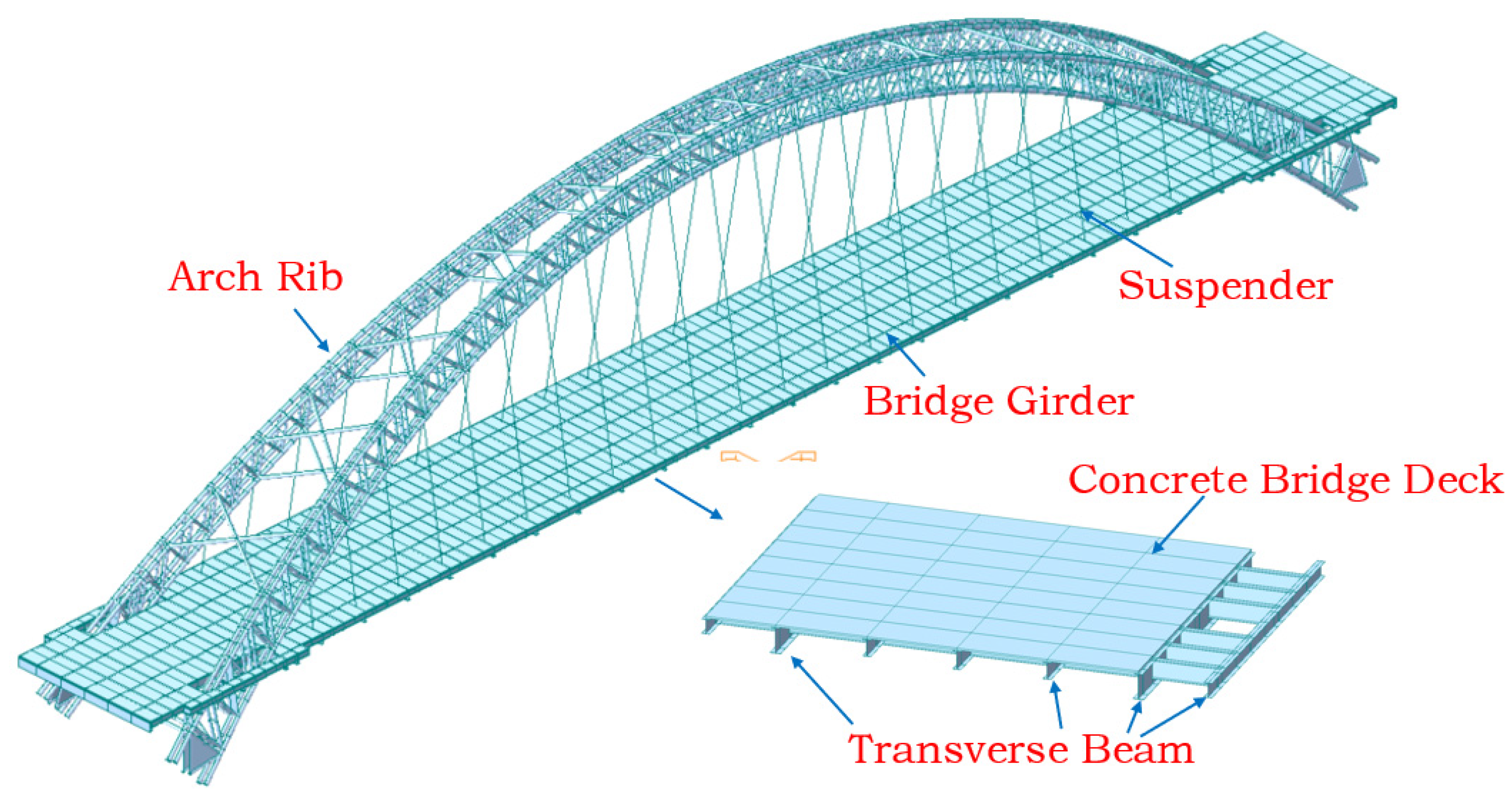
The arch ribs and the steel grid beams were modeled using beam elements, the bridge slab was modeled using plate elements, and the suspenders were modeled using truss elements. The entire bridge has a total of 3930 nodes and 5714 elements, including 4942 beam elements, 724 plate elements, and 48 truss elements. The abutments were fixed. The suspenders and arch ribs were rigidly connected using elastic connections. The supports at two ends of the main girder were modeled as simply supported. The second-stage load, such as the pavement and parapet, was simulated using uniformly distributed loads applied to the main girder. The types and quantities of elements used in the model are shown in Table 2. The finite element model is shown in Figure 4.
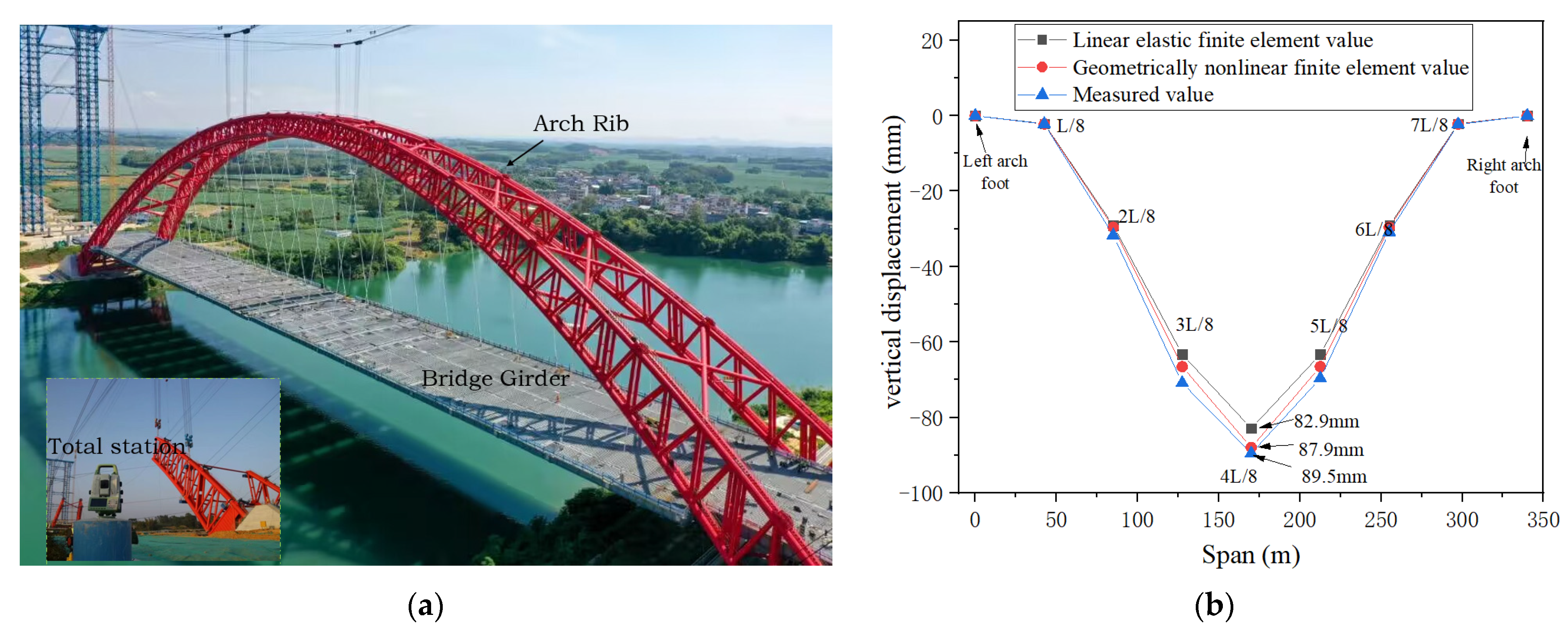
To verify the accuracy of the finite element model, the measured vertical displacement of the arch ribs during construction was compared with the finite element values. Reflectors are arranged at the center of the top chord of the arch rib at the key sections (i.e., L/8, 2L/8, 3L/8, 4L/8, 5L/8, 6L/8, and 7L/8). A Leica total station was used to measure the vertical displacement of the arch rib before and after the installation of the bridge deck. The resolution of the total station is 0.1 mm. To avoid the impact of solar radiation on structural deformation, measurements were made in the early morning with similar atmospheric temperatures. Meanwhile, the displacements of ribs induced by bridge deck installation were calculated by the FE model. Two strategies were used during the calculation (i.e., the geometric nonlinearity strategy and the linear elastic strategy). Figure 5a is the on-site construction drawing, and Figure 5b is a comparison between the measured values and calculated values of the vertical displacement at key sections of the arch rib. The deviation is shown in Table 3 as well. In both strategies, the calculated vertical displacement of the key section of the arch rib matches the measured value. The geometric nonlinearity strategy has slightly better performance than the linear elastic strategy, but it is not significant.
In the table, (1) is the linear elastic finite element value, (2) is the geometrically nonlinear finite element value, and (3) is the measured value.
3. Analysis of Reasonable Value of Arch Rib Inclination Angle
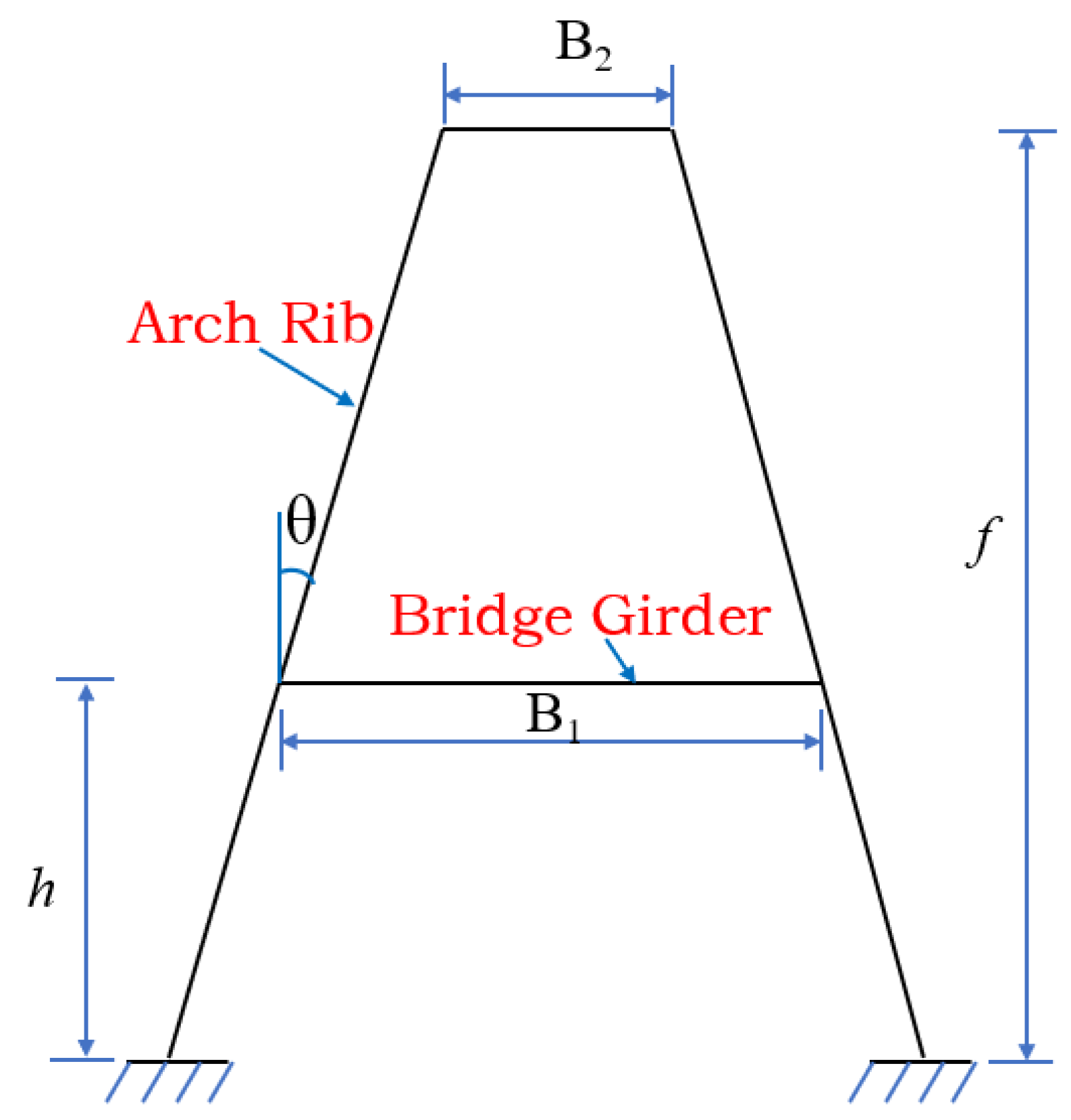
For the basket-handle through the arch bridge, the inclination angle of the arch rib cannot infinitely increase due to the geometrical limit. The width and height of the bridge deck, the arch rise, and other factors are shown in Figure 6. The relationship between the inclination angle of the arch rib and these parameters can be expressed as follows:
The arch rib inclination angle is:
where —Arch rib inclination angle;
—The bridge deck width between the arch ribs;
—The clear distance between arch ribs at the crown;
—Rise of the arch;
—The height from the bridge deck to the center of the arch foot.
When the inclination angle is too large, the arch ribs at the top of the arch will intersect, thereby limiting the increase in the inclination angle. On the other hand, a too-small inclination angle will not be able to take advantage of the benefits of the basket-handle arch. A typical basket-handle arch adjusts the inclination angle of the arch ribs by keeping the bridge deck width constant. For the Shawei Zuojiang Bridge, = 28 m, = 75 m, = 16.2 m. When the inclination angle is zero, = 0°, it is a parallel arch. The inclination angle reaches its maximum value when = 0, which can be calculated by the formula.
Therefore, the range of inclination angles for arch ribs is 0~13°. To analyze the mechanical performance with different rib inclination angles, 0°, 1°, 2°, 3°, 4°, 5°, 6°, 7°, 8°, 9°, 10°, 11°, 12°, and 13° were employed in this study. The natural vibration characteristics, linear elastic stability coefficient, internal force, and displacement of arch ribs under static load were calculated for structures at each selected angle. The optimal range of inclination angle for arch ribs was then determined by considering all the mechanical performances above comprehensively.
3.1. Analysis of the Influence of Natural Vibration Characteristics
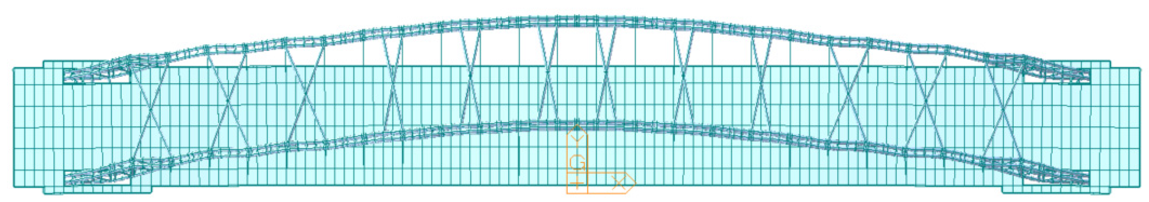
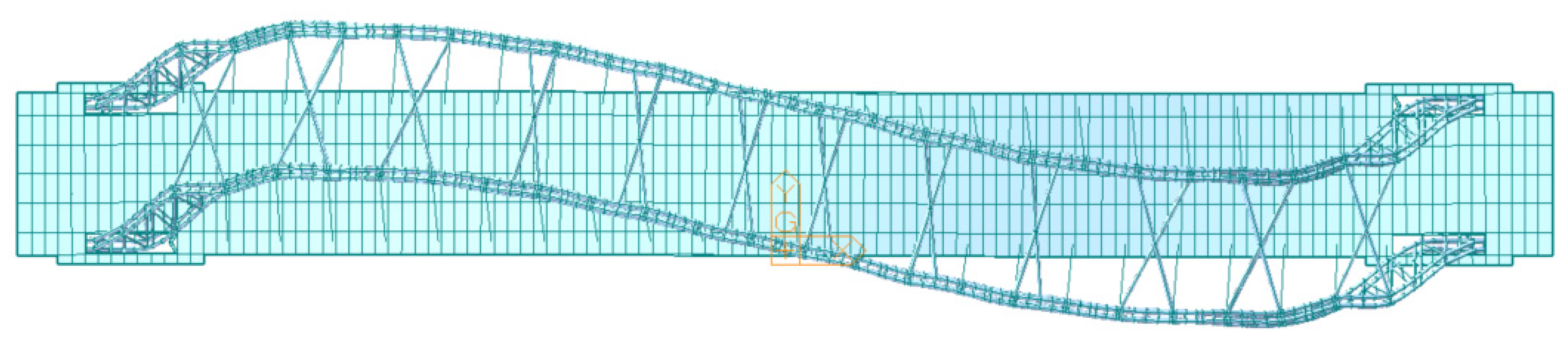
To evaluate the natural frequencies and modes of vibration of the bridge under different arch rib inclinations, the structural self-weight and second stage loads (i.e., the weight of the bridge pavement and the parapet) were considered as the loads. As a result, low-frequency modes contain the majority of the energy, while high-order modes have a negligible impact on the structure’s vibration. For the parallel arch (with an inclination angle of 0°), the first six mode shapes and their natural frequencies are shown in Table 4. The first three mode shapes are shown in Figure 7, Figure 8 and Figure 9.
According to the analysis in Table 4 and Figure 7, Figure 8 and Figure 9, the first six modal frequencies of the bridge have a maximum value of 0.8586, indicating that it is a flexible structure. The first two modes were dominated by lateral bending and vertical bending. Torsion mode was ranked as the sixth mode. It indicated that the structure has a relatively weak lateral stiffness, moderate vertical stiffness, and a relatively strong torsional stiffness. To investigate the modal frequency variation with respect to different inclination angles, the modal frequencies under different inclination angles were compared with those of the parallel arch. The percentage difference of each modal frequency with respect to the parallel arch model is shown in Figure 10.
According to Figure 10, the changing rate varied with different modes while increasing the inclination angle. For the first, third, and sixth modes, the curve shows a pattern of increasing first and then decreasing. The natural frequency of the first, third, and sixth modes reached a maximum value at 8° to 10°, indicating the optimal inclination angle for transverse and torsional stiffness improvement. For the second mode, the natural frequency gradually decreases with an increase in the inclination angle. However, the decrease was small—less than 2% at the inclination angle of 8° to 10°. It indicated that the increase in the inclination angle of the arch rib reduced the vertical stiffness of the arch rib, but the effect was small.
3.2. Linear Elastic Stability Analysis
The linear elastic stability coefficient (λ) is an important indicator for evaluating the stability and safety of structures. The definition of λ can be found in Cao et al. [9], Xu et al. [19], and Wang et al. [25]. Due to the complexity of the structure, it is difficult to obtain its elastic instability limit load using analytical methods. However, using finite-element numerical analysis methods can yield reliable results [25]. Midas Civil employed the subspace iteration method to calculate λ and the buckling shape of each buckling mode by inputting the load conditions, number of buckling modes, and convergence conditions of structural buckling. The change in inclination angle leads to a change in buckling capacity. Under certain loads, the linear elastic stability coefficient λ increases with the increase in buckling capacity. Therefore, λ can be used as an indicator of structural stability. The dead load was employed as the load condition herein because it is the dominant load on the linear stability of the structure. In practice, only the first buckling mode is important because it has the smallest linear elastic stability coefficient. The shape and λ of the first buckling mode were calculated for both in-plane and out-of-plane buckling. The λ buckling shape of the parallel arch ribs is shown in Table 5. The corresponding buckling shape diagrams are shown in Figure 11 and Figure 12.
According to Table 5 and Figure 11 and Figure 12, the first buckling modes of the parallel arch are the anti-symmetric transverse bending and the anti-symmetric vertical bending for out-of-plane buckling and in-plane buckling, respectively. The linear elastic stability coefficient of the out-of-plane buckling is smaller than that of the in-plane buckling for the parallel arch. It indicated that the lateral stiffness of the arch rib is weaker than the vertical stiffness of the parallel arch. The percentage difference of λ with respect to the parallel arch under different arch rib inclination angles is shown in Figure 13.
According to Figure 13, when the inclination angle of the arch rib ranges from 0° to 13°, the λ for the out-of-plane and in-plane directions showed different changing patterns with the increase of the inclination angle. The λ of out-of-plane increased at the beginning and then decreased with the increase in inclination angle. It reached its peak at an inclination angle of 9° with a 20.2% improvement and then sharply decreased after the inclination angle exceeded 10°. The λ of in-plane mode showed a negative correlation with the inclination angle. The decrease was small (3%) when the inclination angle was less than 10°. However, the λ of in-plane mode decreases significantly when the inclination angle exceeds 10°. The results indicated that the optimal inclination angle of the arch rib is between 8° and 10°. It effectively improves the out-of-plane stability of the structure with an insignificant decrease in in-plane stability. Therefore, it is recommended to use an appropriate inclination angle of 8° to 10° for the arch rib while ensuring the optimal first-order stability safety factors for both the out-of-plane and in-plane directions.
In order to consider the impact of geometric nonlinearity on the stability of the structure, the λ of the parallel arch was calculated using a geometric nonlinear model. The results are shown in Table 6.
From Table 6, it can be observed that, considering the geometric nonlinearity of the structure, the λ is smaller with respect to that of the linear elastic model. However, the difference is not significant, with 1.5% for out-of-plane mode and 5.86% for in-plane mode. Therefore, the geometric nonlinearity of the structure is no longer considered.
3.3. Static Performance Analysis
Deformation and internal forces are macroscopic manifestations of the stress state of bridges [26,27], and the internal forces of an arch bridge are mainly affected by the dead load. As the span increases, the proportion of internal forces generated by the dead load becomes larger. Therefore, the analysis of the effect of dead loads on the internal forces of arch bridges is essential [28,29]. The dead load-induced internal forces and displacements of the arch rib were calculated under different inclination angles. As a result, the arch rib is a symmetrical structure, and the arch foot, L/8, 2L/8, 3L/8, and 4L/8 (arch top) were selected as the key sections for displacement analysis. The key sections for internal force selection were the arch foot, L/4, and 4L/8 (arch top). For a parallel arch, the vertical displacements of the arch rib at the arch foot (L/8, 2L/8, 3L/8, and 4L/8) are 0, −16.5 mm, −83 mm, −162.8 mm, and −208.8 mm, respectively. Figure 14 shows the difference in displacement for different arch rib inclination angles with respect to a parallel arch.
According to Figure 14, with the increase in the inclination angle, the vertical displacements of the L/8 and 2L/8 sections show a continuous increase. When the inclination angle is less than 10°, the vertical displacement changes slowly, but it increases rapidly in later stages. Vertical displacement at L/8 shows the largest percentage increase of 10% at the inclination angle of 13°. However, the vertical displacement value of the L/8 section is relatively small. The 3L/8 and 4L/8 sections show a trend of first decreasing and then increasing. The vertical displacement percentage difference reached its smallest for both 3L/8 and 4L/8 sections when the inclination angle was 8°. It indicated that when the inclination angle of the arch rib is 8°, the vertical displacement of the 3L/8 section and the 4L/8 section of the arch rib is the smallest, and the percentage difference is less than 5%. As far as the vertical displacement of the arch rib is concerned, the influence of the inclination angle on the vertical displacement of the structure is not significant.
For the parallel arch, the internal forces of the key sections of the arch ribs are shown in Table 7. The axial force unit in the table is kN and the moment unit is kN·m. The internal force differences of different inclinations with respect to a parallel arch are shown in Figure 15.
From Table 7 and Figure 15, the axial force of each key section of the arch rib shows a different trend with the increase of the inclination angle. The axial forces at the upper chord arch top section and the lower chord 2L/8 section decrease with the inclination angle when the inclination angle is less than 10° and then increase. The axial force of the other key sections of the arch rib shows an increasing trend, but the percentage difference is less than 5%, and the change in axial force is relatively small. The bending moment of different sections also shows different trends. The bending moment of the upper chord arch foot section increases with the arch rib inclination angle at first and then decreases. It reached a peak when the inclination angle was 10° with a 30% larger parallel arch. The effects of inclination angle on bending moments at other key sections are not significant.
4. Conclusions
Based on the world’s largest CFST basket-handle arch bridge, this paper conducted a study on the effect of changes in arch rib inclination angle on the mechanical performance of large CFST basket-handle arch bridges. Different arch rib inclination angles were analyzed in terms of structural natural frequency, linear elastic stability, internal forces, and displacement under static load. The relationship between mechanical performance and arch rib inclination angle was systematically studied, and the following main conclusions were obtained:
(1) According to the analysis of the vibration characteristics, it is recommended that the reasonable range of the rib inclination angle be 8° to 10°, with the optimal angle being 9°. At this angle, not only does the second-order natural frequency of the structure change slightly, but the first, third, and sixth-order natural frequencies are also increased, which can effectively improve the rib’s lateral and torsional stiffness.
(2) Based on the analysis of the structural elastic stability coefficient, it is suggested that the reasonable range of the arch rib inclination angle is 8~10°, and the optimal angle is 9°. This not only ensures the best out-of-plane stability of the arch rib, with a stability improvement of 20.2% compared to a parallel arch but also ensures that the decrease in in-plane stability is within 3%.
(3) Based on the analysis of static performance, the variation of rib inclination angle has little effect on rib displacement and internal force. When the rib inclination angle varies within the range of 0° to 13°, the difference ratio of rib displacement is within 5%. The bending moment difference ratio of the upper chord foot section reaches 30% at an inclination angle of 10°, but the bending moment value is relatively small. Considering the relationship between rib displacement and internal force with rib inclination angle, it is suggested that the rib inclination angle be between 9° and 10°.
(4) Based on the above analysis of the structural mechanics performance under different rib inclination angles, it is recommended that the optimal range of inclination angle for the arch rib should be 8–10° for the 300-m-class CFST arch bridge.
In the future, further research will be conducted by considering material nonlinearity, geometric nonlinearity, and material nonlinear coupling effects. Additionally, CFST arch bridges with different span lengths will be investigated as well.
Author Contributions
Z.L. and Y.W., methodology and finite element analysis; C.W. and Y.F., drawing and translation; C.L. and S.W., review and editing. All authors have read and agreed to the published version of the manuscript.
Funding
The support from the Guangxi Key R&D Plan (Guike AB22036007), the National Natural Science Foundation Youth Fund Project (51608080), the Chongqing Natural Science Foundation General Project (CSTC2021jcyj-msxm2491), The Science and Technology Innovation Project of the Chongqing Education Commission for the Construction of the Chengdu Chongqing Double City Economic Circle (KJCXZD2020032), and the Special Key Project for Technological Innovation and Application Development in Chongqing (CSTB2022TIAD-KPX0205) are greatly acknowledged.
Data Availability Statement
Data is available on request due to restrictions.
Conflicts of Interest
The authors declare no conflict of interest.
Abbreviations
| Symbol | Illustrate |
| L | Calculated span |
| f | Calculate rise-to-span ratio |
| m | arch-axis coefficient |
| Arch rib inclination angle | |
| λ | Structural stability safety factor |
| N | axial force |
| M | bending moment |
References
- Chen, B.C.; Wei, J.G.; Zhou, J. Application status and Prospect of concrete filled steel tubular arch bridges in China. J. Civ. Eng. 2017, 50, 12. (In Chinese) [Google Scholar] [CrossRef]
- Hu, C.F.; Huang, Y.M. In-plane nonlinear elastic stability of pin-ended parabolic multi-span continuous arches. Eng. Struct. 2019, 190, 435–446. [Google Scholar] [CrossRef]
- Chen, B.C.; Liu, J.P. Summary of World Arch Bridge Construction and Technical Development. J. Transp. Eng. 2020, 20, 27–41. (In Chinese) [Google Scholar] [CrossRef]
- Zheng, J.; Wang, J. Concrete-Filled Steel Tube Arch Bridges in China. Engineering 2017, 4, 143–155. [Google Scholar] [CrossRef]
- Chen, B.C.; Wang, T.L. Overview of Concrete Filled Steel Tube Arch Bridges in China. Pract. Period. Struct. Des. Constr. 2009, 14, 70–80. [Google Scholar] [CrossRef]
- Rajeev, S.; John, P.D.; Varkey, M.V. Study of concrete filled steel tubular arch bridge: A review. Appl. Mech. Mater. 2016, 857, 261–266. [Google Scholar] [CrossRef]
- Hu, J.H. Analysis of Basic Dynamic Characteristics of a Steel Tube Concrete Basket Arch Bridge. J. Nanchang Univ. (Eng. Ed.) 2019, 41, 144–148+156. (In Chinese) [Google Scholar]
- Zhang, Q.M.; Zhou, G. Research on the influence of the lateral inclination angle of the arch ribs on the stability of large-span basket arches. Bridge Constr. 2007, 37, 32–34. (In Chinese) [Google Scholar]
- Cao, Z.Z.; Feng, Y.T.; Shen, F.J. Spatial Stability Analysis of Long Span Steel Box Basket Arch Bridge. Bridge Constr. 2011, 205, 43–47. (In Chinese) [Google Scholar]
- Bonopera, M.; Chang, K.C.; Chen, C.C.; Lin, T.K.; Tullini, N. Bending tests for the structural safety assessment of space truss members. Int. J. Space Struct. 2018, 33, 026635111880412. [Google Scholar] [CrossRef]
- Maes, K.; Peeters, J.; Reynders, E.; Lombaert, G.; De Roeck, G. Identification of axial forces in beam members by local vibration measurements. J. Sound Vib. 2013, 332, 5417–5432. [Google Scholar] [CrossRef]
- Yang, Y. Design and Research on Long Span Concrete Filled Steel Tubular Arch Bridges for Heavy Haul Railways. Railw. Stand. Des. 2018, 62, 107–111+186. (In Chinese) [Google Scholar] [CrossRef]
- Yun, D.; Liu, H.; Zhang, S.M. Natural vibration characteristics and stability of large-span through steel tube concrete arch bridges. J. Jilin Univ. (Eng. Ed.) 2013, 43, 86–91. (In Chinese) [Google Scholar] [CrossRef]
- Wang, L.; Peng, R.H.; Guo, X.R. The effect of arch rib inclination angle on the dynamic response of steel tube concrete basket arch bridges. J. Railw. Sci. Eng. 2012, 9, 25–29. (In Chinese) [Google Scholar] [CrossRef]
- Wei, J.G.; Chen, J.W.; Xie, Z.T. Construction and analysis of a steel tube concrete dumbbell shaped cross-section basket shaped standard arch bridge. J. Fuzhou Univ. (Nat. Sci. Ed.) 2019, 47, 663–668. (In Chinese) [Google Scholar] [CrossRef]
- Zeng, D.R.; Zhang, Q.M. The influence of the inclination angle of the arch rib of a basket arch bridge on lateral stability. J. Chongqing Jiaotong Univ. 2006, 25, 4–8. (In Chinese) [Google Scholar] [CrossRef]
- Zhao, Y.Y.; Lao, W.Q.; Feng, R. Analysis of the influence of internal inclination angle on the mechanical properties of steel tube concrete basket arches. Highw. Transp. Technol. 2007, 24, 56–58+89. (In Chinese) [Google Scholar]
- Huang, P.M.; Ren, X.; Li, W.J. The influence of arch rib inclination angle on the static and dynamic behavior of steel tube concrete arch bridges. J. Chang. Univ. (Nat. Sci. Ed.) 2009, 29, 51–55. (In Chinese) [Google Scholar]
- Xu, H.; Wu, Y.T.; Xie, W.W. Research on Reasonable Arch Rib Inclination of CFST Arch Bridges for 400 m Railway. J. Railw. Sci. Eng. 2021, 18, 1203–1212. (In Chinese) [Google Scholar]
- Wang, D.; Yao, X.L.; Yan, W.F. Analysis of the Influence of the Optimal Inclination Angle of the Arch Ribs of a Through Type Basket Arch Bridge. Transp. Sci. Eng. 2022, 38, 60–64+71. (In Chinese) [Google Scholar] [CrossRef]
- Ji, R.C.; Shi, M.X. Stability Analysis of Long Span Railway Steel Pipe Concrete Tied Arch Bridges. Vib. Impact 2011, 30, 87–91. (In Chinese) [Google Scholar] [CrossRef]
- Pan, S.S.; Zhang, Z.; Huang, C.L. Research on the influence of the inclination angle of the X-shaped double rib arch on lateral stability. J. Dalian Univ. Technol. 2008, 06, 845–850. (In Chinese) [Google Scholar] [CrossRef]
- Li, S.; Xin, J.; Jiang, Y.; Wang, C.; Zhou, J.; Yang, X. Temperature-induced deflection separation based on bridge deflection data using the TVFEMD-PE-KLD method. J. Civ. Struct. Health Monit. 2023, 13, 781–797. [Google Scholar] [CrossRef]
- Liu, Z.; Zhou, S.; Zou, K.; Qu, Y. A numerical analysis of buckle cable force of concrete arch bridge based on stress balance method. Sci. Rep. 2022, 12, 12451. [Google Scholar] [CrossRef]
- Wang, Q.; Wang, C.S.; Yu, X. Local Stability Test and Numerical Analysis of Steel Bridge Towers. J. Chang. Univ. (Nat. Sci. Ed.) 2008, 127, 67–72. (In Chinese) [Google Scholar]
- Xin, J.; Jiang, Y.; Zhou, J.; Peng, L.; Liu, S.; Tang, Q. Bridge deformation prediction based on SHM data using improved VMD and conditional KDE. Eng. Struct. 2022, 261, 114285. [Google Scholar] [CrossRef]
- Xin, J.; Zhou, C.; Jiang, Y.; Tang, Q.; Yang, X.; Zhou, J. A signal recovery method for bridge monitoring system using TVFEMD and encoder-decoder aided LSTM. Measurement 2023, 214, 112797. [Google Scholar] [CrossRef]
- Geng, Y.; Ranzi, G.; Wang, Y.T. Out-of-plane creep buckling analysis on slender concrete-filled steel tubular arches. J. Constr. Steel Res. 2018, 140, 174–190. [Google Scholar] [CrossRef]
- Liu, C.Y.; Hu, Q.; Wang, Y.Y. In-plane stability of concrete-filled steel tubular parabolic truss arches. Int. J. Steel Struct. 2018, 18, 1306–1317. [Google Scholar] [CrossRef]
Figure 1.
Arch rib structure diagram. (a) Schematic diagram of arch rib inclination angle; (b) arch rib arch crown section; and (c) arch rib and arch foot section.
Figure 1.
Arch rib structure diagram. (a) Schematic diagram of arch rib inclination angle; (b) arch rib arch crown section; and (c) arch rib and arch foot section.

Figure 2.
Elevation of Shawei Zuojiang Bridge.

Figure 3.
Cross section of the main beam.

Figure 4.
Finite element model diagram.

Figure 5.
(a) Construction drawing of bridge deck installation Site. (b) Comparison of vertical displacement of key sections of arch rib.
Figure 5.
(a) Construction drawing of bridge deck installation Site. (b) Comparison of vertical displacement of key sections of arch rib.

Figure 6.
Schematic diagram of arch rib inclination calculation.

Figure 7.
Symmetrical transverse bending of the main arch.

Figure 8.
Antisymmetric vertical bending of the main beam and arch rib.

Figure 9.
Antisymmetric transverse bending of the main arch.

Figure 10.
Natural frequency difference of different arch rib angles and parallel arches.

Figure 11.
Out-of-plane buckling shape of a parallel arch plane.

Figure 12.
In-plane buckling shape of a parallel arch plane.

Figure 13.
Percentage difference of the linear elastic stability coefficient with respect to parallel arch.
Figure 13.
Percentage difference of the linear elastic stability coefficient with respect to parallel arch.

Figure 14.
Vertical displacement difference with respect to parallel arch at key sections.

Figure 15.
Internal force difference of arch ribs at different arch rib angles with respect to parallel arch. (a) Axial force and (b) bending moment.
Figure 15.
Internal force difference of arch ribs at different arch rib angles with respect to parallel arch. (a) Axial force and (b) bending moment.


Table 1.
Partial basket-handle arch bridges were built in China.
| Serial Number | Bridge Name | Span/m | Arch Rib Section Form | Inclination Angle |
|---|---|---|---|---|
| 1 | The Yarlung Zangbo River | 430 | Four limb truss | 4.6° |
| 2 | Yellow River Extra Large Bridge | 380 | Four limb truss | 8° |
| 3 | Guangxi Shawei Zuojiang Bridge | 360 | Four limb truss | 10° |
| 4 | Lancang River Grand Bridge | 342 | Four limb truss | 6.8 |
| 5 | Anhui Taiping Lake Bridge | 336 | Four limb truss | 10° |
| 6 | Zhejiang Sanmenkou Cross Sea Bridge | 270 | Dumbbell shaped | 8° |
| 7 | Zhejiang Tongwamen Bridge | 238 | Dumbbell shaped | 8.5° |
| 8 | Jinghang Canal Grand Bridge | 235 | Four limb truss | 10° |
| 9 | Menghua Railway Longmen Yellow River Bridge | 202 | Four limb truss | 6° |
| 10 | Huayudong Bridge | 180 | Four limb truss | 10° |
| 11 | Jiangning Grand Bridge | 128 | Dumbbell shaped | 9° |
| 12 | Hujiawan Grand Bridge | 112 | Dumbbell shaped | 9° |
| 13 | Dongtiaoxi Grand Bridge | 112 | Dumbbell shaped | 13° |
| 14 | Longmen Yellow River Bridge | 202 | Four limb truss | 6° |
Table 2.
Element type and quantity.
| Element Type | Quantity | |
|---|---|---|
| Arch Rib | Beam | 3080 |
| Steel lattice beam | Beam | 1862 |
| Bridge deck | Plate Element | 724 |
| Suspender | Truss Element | 48 |
Table 3.
The deviation between calculated values and measured values of vertical displacement at key sections of arch ribs (mm).
Table 3.
The deviation between calculated values and measured values of vertical displacement at key sections of arch ribs (mm).
| L/8 | 2L/8 | 3L/8 | 4L/8 | 5L/8 | 6L/8 | 7L/8 | |
|---|---|---|---|---|---|---|---|
| (3)—(1) | −0.1 | −2.6 | −7.6 | −6.6 | −6.3 | −1.7 | −0.2 |
| (3)—(2) | 0.0 | −2.1 | −4.3 | −1.6 | −3.1 | −1.3 | −0.1 |
Table 4.
Natural frequency and mode direction of the first six modes.
| Modal | Natural Frequency (HZ) | Vibration Mode Direction |
|---|---|---|
| 1 | 0.32 | Symmetrical transverse bending of the main arch |
| 2 | 0.53 | Antisymmetric vertical bending of the main beam and arch rib |
| 3 | 0.55 | Antisymmetric transverse bending of the main arch |
| 4 | 0.64 | Symmetrical transverse bending of the main beam and arch rib |
| 5 | 0.73 | Symmetrical vertical bending of the main beam and arch rib |
| 6 | 0.86 | Symmetrical torsion of the main beam and arch rib |
Table 5.
First-order stability coefficient and instability mode of a parallel arch.
| Working Condition | Modal | Linear Elastic Stability Coefficient λ | Buckling Shape |
|---|---|---|---|
| Dead Load | Out-of-plane 1st bucking mode | 7.447 | Antisymmetric transverse bending of the main arch |
| In plane 1st bucking mode | 15.69 | Antisymmetric vertical bending of the main arch |
Table 6.
Stability comparison.
| λ of Out-of-Plane Mode | λ of In-Plane Mode | |
|---|---|---|
| Linear elastic model | 7.447 | 15.69 |
| Geometric nonlinear model | 7.335 | 14.77 |
| Difference percentage (%) | −1.50 | −5.86 |
Table 7.
Internal force values of key sections of parallel arches.
| Internal Force | Position | Arch Foot Section | 2L/8 Section | 4L/8 Section |
|---|---|---|---|---|
| Axial Force (kN) | Upper chord | −13,995.48 | −18,325.64 | −22,800.5 |
| Lower chord | −22,804.11 | −21,297.89 | −13,871.3 | |
| Bending Moment (kN·m) | Upper chord | 124.67 | −164.95 | 487.35 |
| Lower chord | −984.09 | −87.74 | 670.42 |
Disclaimer/Publisher’s Note: The statements, opinions and data contained in all publications are solely those of the individual author(s) and contributor(s) and not of MDPI and/or the editor(s). MDPI and/or the editor(s) disclaim responsibility for any injury to people or property resulting from any ideas, methods, instructions or products referred to in the content. |
© 2023 by the authors. Licensee MDPI, Basel, Switzerland. This article is an open access article distributed under the terms and conditions of the Creative Commons Attribution (CC BY) license (https://creativecommons.org/licenses/by/4.0/).
Share and Cite
MDPI and ACS Style
Liu, Z.; Wu, Y.; Wang, C.; Fan, Y.; Luo, C.; Wang, S. Research on Optimal Arch Rib Inclination of Large Span Highway CFST through Arch Bridge. Buildings 2023, 13, 1415. https://doi.org/10.3390/buildings13061415
AMA Style
Liu Z, Wu Y, Wang C, Fan Y, Luo C, Wang S. Research on Optimal Arch Rib Inclination of Large Span Highway CFST through Arch Bridge. Buildings. 2023; 13(6):1415. https://doi.org/10.3390/buildings13061415
Chicago/Turabian StyleLiu, Zengwu, Yuexing Wu, Chengwei Wang, Yonghui Fan, Chao Luo, and Shaorui Wang. 2023. "Research on Optimal Arch Rib Inclination of Large Span Highway CFST through Arch Bridge" Buildings 13, no. 6: 1415. https://doi.org/10.3390/buildings13061415
Note that from the first issue of 2016, this journal uses article numbers instead of page numbers. See further details here.