Lenz’s Law of Electromagnetic Induction
What is Lenz’s Law of Electromagnetic Induction
What is Lenz’s Law?
According to the Lenz’s law (which was introduced by a Russian of Baltic German physicist Heinrich Friedrich Emil Lenz in 1834), the direction of current can be found. when the current through a coil changes magnetic field, the voltage is created as a result of changing magnetic field, the direction of the induced voltage is such that it always opposes the change in current.
Lenz’s law entails how the direction of an induced EMF in a coil can be determined. “It thus states that the direction of induced EMF is such that it opposes the change causing it.
In other words, The Lenz’s law states that when an E.M.F is induced in a circuit, the current setup always opposes the motion, or change in current, which produces it. OR
An induced EMF will cause a current to flow in a close circuit in such a direction that its magnetic effect will oppose the change that produced it.
In very simple words, Lenz’s law states that the induced effect is always such as to oppose the cause that produced it.
Explanation of Lenz’s Law
Lenz’s law (which is a little bit tricky and confusing for newbies) can be understood with the help of the above diagram where an insulated coil is connected to a sensitive galvanometer and a static and solid bar magnet. Let’s see how it works
- When both the bar magnet and coil is in static position, no current flowing or induced EMF (even the small amount of flux (N pole’s of static magnet bar) linked to the coil movement), hence, no deflection in the galvanometer.
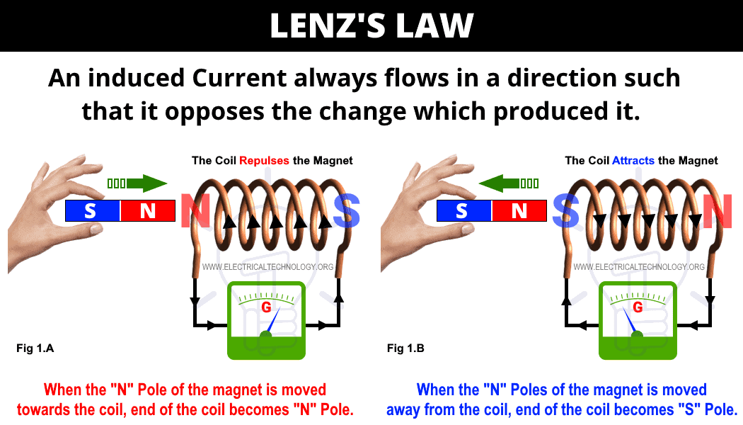
- When the magnet bar moves quickly towards the coil, there is rapid deflection in the galvanometer for an instance. Keep in mind that the deflection will remain constant until the continuous movement of the magnet bar with respect to the coil (i.e. relative moment between magnet bar and coil). If both the magnet bar and coil achieve the static position, the deflection of the galvanometer will be at Zero position (as shown in fig 1 A).
- When the magnet bar is moved away from the coil, there will be again a deflection in the galvanometer until the relative movement between magnet bar and coil becomes at rest or static position. Keep in mind the direction of the galvanometer is in the opposite direction with the respect of fig 1A (as shown in fig 1 B).
- The same happens (Step 2 & 3) if the magnet bar is in a static position while the coil moves towards or moves away from the static magnet bar.
It clearly shows that when the magnet bar (in movement) is near to the coil, it cuts or links to the large portion of flux whereas, the rate of flux linkage is less in case when magnet bar moves away from the coil.
The deflection in the galvanometer shows the induced EMF in the coil which caused by all of sudden moving towards or moving away the magnet bar to the coil. The exact reason for induced EMF is the change in flux linkage with respect to the coil which continues until the movement of both magnet bar or coil is stopped. In other words, a strong magnetic field or flux won’t induce EMF in the static conductor. Hence, change in flux is the must have phenomena to induce EMF either in coil or conductors.
The above explanation shows that when the “N” Pole of the magnet is moved towards the coil, EMF induced in the coil and flows the current in it in the anti-clock wise direction (seeing the coil by side), hence, the front end of the coil becomes “N” Pole (fig 1.A).
This way, the magnet’s North pole reflects the N coil’s N pole. A mechanical energy is used to control this repulsive force which converts into electrical energy in the form of EMF in the coil.
Similarly, When the N Pole of the magnet is moved away from the coil, the facing end of the coil becomes “S” Pole. This way, the magnet bar N pole attracts the coil’s S pole. To control this attractive force between coil and magnet bar, again mechanical energy is needed which converts into electrical energy in the form of Induced EMF in the coil.
This proves that the induced current always flows in a direction such that it opposes the change in magnetic field (moving towards/away the magnet bar to the coil) which produced it.
Related Posts:
- Faraday’s Law of Electromagnetic Induction
- Coulomb’s Law of Electrostatics With Example
- Coulomb’s Laws of Magnetic Force – Solved Example
Formula & Equations for Lenz’s Law
The basic version of Lenz’s law can be mathematically expressed as follows.
e = – (dΦB/dt)
Actually, the “-” symbol in the Faraday’s law of electromagnetic induction represents the Len’s law. As it is based on the principle of energy conservation as well as Newton’s third law (every action has an equal reaction but the magnitude is in opposite direction.

Other forms of equations and formulas for Lenz’s law are as follows.
- e = – N (dΦB/dt)
- e = – N (ΔΦ/Δt)
- e = – N (δΦB/δt)
Where:
- e = Induced EMF in the coil/conductor
- N = Number of turns or loops in the coil
- dΦB, ΔΦ, δΦB = Change in the rate of magnetic flux
- dt, Δt, δt = Change in the rate of time
Applications of Lenz’s Law
There multiple uses and applications based on Len’s law e.g. the basic principle of Lenz’s law is used in
- Electromagnetic braking in trains.
- Induction burners, cooktops and induction heating.
- Electric generators/alternators, transformers and motors (back EMF).
- Microphones, card readers, Audio/Video recording tapes, Hard drive and spinning disks and debit/credit cards.
- Eddy current balance.
- Dynamometers and metal detectors.
- To analyze the basic concept of stored energy in the inductors.
Related Posts
- Kirchhoff’s Current & Voltage Law (KCL & KVL) | Solved Example
- Ohm’s Law with Simple Explanation
- Formula & Equations for Ohm’s, Kirchhoff’s & Coulomb’s Laws
- Norton’s Theorem. Easy Step by Step Procedure with Example
- Thevenin’s Theorem. Step by Step Procedure with Solved Example


