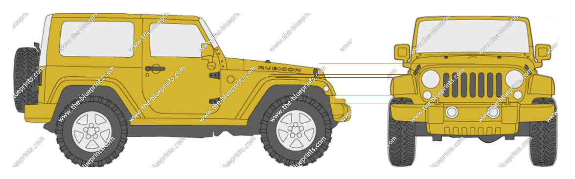
Hi all, I could not figure out what would be the best discussion group would fit my question. So I am hoping, since I need to know some tips on my topic, I thought it might fit best here. However, if this is not the right place, then if a moderator could please let me know instead of ignoring my question. So, without further due, I would like know where people are getting their blueprints for modeling vehicles? I am asking this, because the best place I have heard of is only www.the-blueprints.com However, out of three tries, all of them where unmanageable to fix in Photoshop. I understand that there are some tricks by cropping each projection into single layers and then aligning and scaling each of the projections to make them match. However, I have done as much as I could with the knowledge that I have trying to align each of the projections, and yet, I still fail. The parts where I fail are mostly in the middle of the vehicle. For example, along with the image below I am demonstrating, you can see how the front end bumpers line-up in both projections, as well as the roof of both projections line-up. However, the front fender and the front tip of the hood do not line-up. So any way trying to scale either projection will then disturb the alignments of the bumper and roof.
i find blueprints mostly by searching in google images and look which one is useable. if they dont align perfectly i move my background image slighty. it works perfectly well 
No “blueprints” are flawless, technically speaking those 3-view drawings aren’t even true “blueprints” and since they were drawn by humans, or traced in the case of the vector layouts from the original thick-lined prints, they will never be perfect.
Hence the reason for as much reference material as you can find like photographs of the subject, bad blueprints are just part and parcel of 3D modeling, it’s up to the artist to sort out the details.
Did you draw those ruled lines on the above picture, because the fault is with you, not the “blueprint” as that top line should actually be at the edge of the hood closest to the windshield in the front view, but don’t expect it to line up perfectly because front views are generally always wrong.
It’s up to you, as the 3D artist, to sort that out and use your best judgement. Either that or you can see if Chrysler will sell you a copy of the REAL blueprints.
Actually, the top level configuration drawing gives over all dimension and basic information about the design. It is a off shoot of top level assembly drawing that calls out all the sub level assembly parts and how to put them to gather. So if you want to model that is accurate, you need to start from real parts drawing with real parts dimensions.
Fitz301, yes, these lines where my lines that I drew to demonstrate the problem, but I quite don’t undersand your analogy in regaurds to my top line is wrong. Since when does the nose of the hood in thr front projection is suppose to line-up with side projection’s winsheild??? I have never seen a vehicle ever do that before. As a matter of fact, it is clearly visable that the winshield in both projections are up higher than the highest point of the hood. I just don’t see your analogy at all. Not to be rude, I am just saying that it is confusing me.
@ brokenpixel. I am taking a look at the video now as I type this post, since my internet is to crawl.
@ ridix: just so that we are on the same page, when I say accurate, I just want something that lines-up more than something that gives dimensions to each part.
HI there sawsrinath. That is a pretty good link, but unfortunately I could not find the right jeep I was looking for. I will certainly keep this in mind, since I might need to pick another boxy type vehicle. I am trying to accomplish 2 things. Firstly strengthening my vehicle modeling artistically, and the second part, I need the project to also be simple for paint texturing.